- https://domdigitallab.wordpress.com/2018/12/06/final-project-report/
This first project is a sound visualizer that has more LEDs light up the louder the sound being input is. Though I would imagine it would be relatively easy to create, the flame flickering effect that it has is very unique and I wonder how it was achieved.
https://crysta1ann.wordpress.com/2019/12/11/digital-electronics-final-project-report/
This second project transforms a ukulele into a midi controller using distance sensors. I would be very interested in making a midi controller that I could easily control like a guitar (my primary instrument), so this is a good project to look to.
https://jwelectronicsexperimentlab.wordpress.com/2018/05/02/digital-electronics-lab-2018-final-project-report/
Another audio visualizer, this project creates an animated video depending on the sound that is put in. It would be really cool to flesh the animation program out a bit more, using more shapes besides circles and ovals. - https://www.youtube.com/watch?v=Ow74nWzG-eU
This guy made a guitar pedal that turns basslines into synth basslines, which is really interesting. He seems to have used something called a Pedalshield, but I’m not to certain what that is.
https://create.arduino.cc/projecthub/MrRoboto19/etch-a-sketch-hypercycloid-e72051?ref=platform&ref_id=424_trending___&offset=4
This person made something that you can attach to an etch a sketch and it creates a random geometric shape. It uses motors to turn the wheels and should not be left alone otherwise it might overheat. - In digital electronics terms a switch or button is a digital input, an LED is a digital output, and a potentiometer is a digital input.
- I have some experience programming, I took intro to Computer Programming last semester and was in some Java classes in highschool. I’m not very good at it though.
Lab Report 11
1a. https://neunaber.net/collections/pedals/products/immerse-mk-ii
https://saturnworkspedals.com/product/dark-matter-tube-overdrive-pedal/
https://deepspacedevices.com/product/golem/
I like the warm sound that most of these pedals bring to the guitars that they’re tested with. The art design on most of them are great as well, particularly the dark matter tube overdrive
1b. Larger companies seem to be making more standard, all encompassing pedals, whereas smaller companies are making more unique and specific pedals.
1c. The Korg Miku is a pedal that converts guitar tone into the sound of japanese vocaloid Hatsune Miku’s voice. I have absolutely no idea who would ever want to use this pedal, but there is no denying that it is unique.
2. Latching switch
3. A momentary switch will not remain activated when no longer being activated, whereas a latching switch does. A latching switch is good for turning an effect on or off, whereas a momentary switch is good for a pedal that is only active when held down.
Analog Lab 10
Analog Lab 9
- A
- B
- Yes
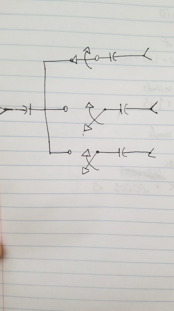
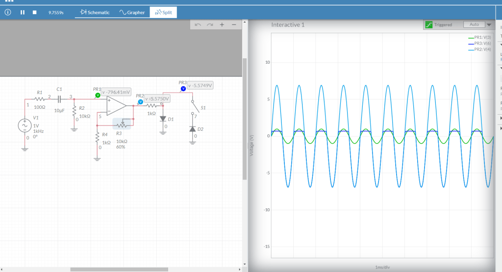
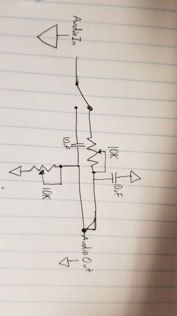
- Below is the schematic for the circuit I made in the video. I’d refer the potentiometer at the end, right before the output circuit, as the “crossfader”. With this circuit, if you turn the crossfader all the way to one side you’ll hear Distortion. If you turn the crossfader all the way to the other side you’ll hear clean audio.
- A mixture of both clean and distorted audio
Analog Lab 8
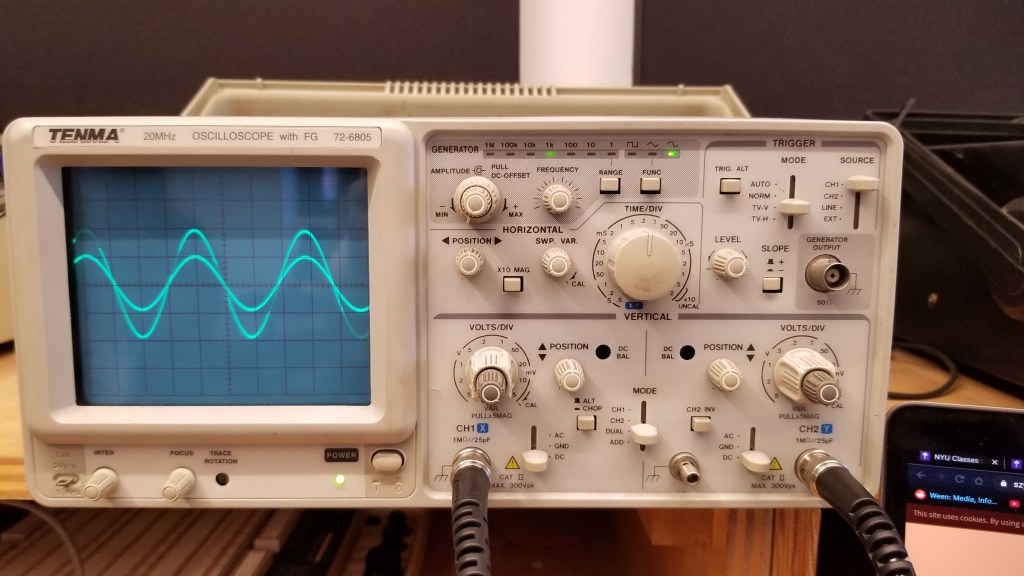
1) With the oscillator we’re studying the comparator outputs a Square wave and the integrator outputs a Triangle wave.
2) With an integrator, if Vin is positive the output voltage ramps down (up/down). If Vin is negative the output voltage ramps up (up/down).
3) With a comparator, if the op amp’s + input is connected to a greater voltage that that connected to it’s – input, the op amp’s output will be about positive (positive/negative) 9v DC. If the op amp’s + input is connected to a lower voltage that that connected to it’s – input, the op amp’s output will be about negative (positive/negative) 9v DC.
4) There’s a formula for how fast the integrator ramps up or down:
change in volts per second at Vout = -Vin / RC
So the bigger the resistance R you use the slower (faster/slower) the ramp gets, and the bigger the capacitor gets the slower (faster/slower) the ramp gets.
5) The circuit at the end of this video is a monophonic synthesizer – it can only output one tone at a time. What do you think would have to do to make a polyphonic synthesizer that could play 2 notes at the same time? 3 notes? 4 notes? 100 notes?
You would need to make a new circuit for each note you would want to be able to play at the same time.
Lab Report 7
Lab Report 6
2a.
C = 1 / (2 x 3.14 x 10 x 20,000)
C = 1 / (2 x 3.14 x 10,000 x 20)
Pot = 10k
Capacitor = 10uF
2b.
2c. C = 1 / (2 x 3.14 x 10 x 20,000)
C = 1 / (2 x 3.14 x 10,000 x 20)
2d.
Switch Circuit:
4. In order to increase the dB per octave filter, the resistance must be increased.
5. I think I could build a multi-effect processor like Connor Riley, specifically with the distortion and tremolo parts of the processor. I already know how to build the high pass and low pass filters, so I don’t think it would be too difficult to build.
I might like to build an effects processor with distortion and tremolo like mentioned above, and I’d like to ask the teacher about what other effects might be possible for this class. I’d like to do something cool, though I’m not sure what.
I’d like to be able to build the Boss DS-1 Distortion pedal, it sounds fantastic and it would super cool to build one myself. Maybe as part of an effects rack, though that might be a bit much.
Optional: Headphone-safe circuit
Lab Report 5
- Adding a resistor and a capacitor to the inputs and outputs prevents electricity from flowing the wrong way if you make a mistake, which could break something or cause a fire.
- Gain = (1 + 10k/10k)
Gain = 2
3.
Pot turned to max:
Gain = (1 + 10k/10k)
Gain = 2
Pot turned to min:
Gain = (1 + 10k/10k)
Gain = (1 + 0/10k)
Gain = 1
4. Gain = -22k / 10k
Gain = -2.2
Here the wave being output is inverted as well as being amplified.

5.
Pot turned to max:
Gain = -10k / 4.7k
Gain = -2.13
Pot turned to min:
Gain = 0 / 4.7k
Gain = 0
6. Photocell
Lab Report 4
2.
The “Mode” switch should be set to “Dual” (not pictured here). This makes sure that both inputs are being shown at the same time.
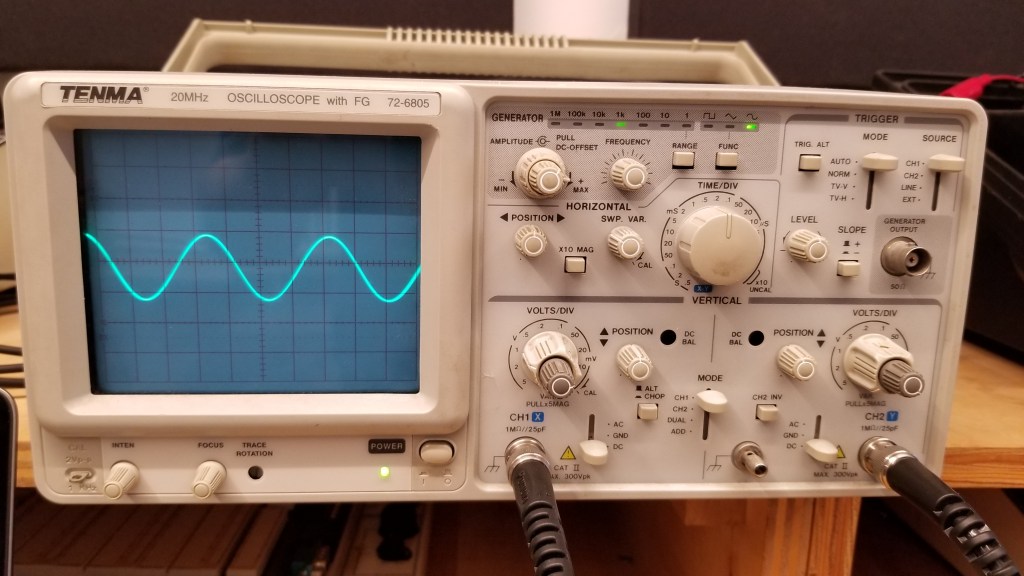
The Horizontal position knob should be facing straight up, otherwise the image will be offset to the left or right.
The Vertical Position knobs should be set facing straight up, other wise the image will be offset up or down.
Both Switches on the bottom should be set to DC, as for this experiment we were measuring Direct Current, not Ground or Alternating Current.
The Time/Div (Time Per Div) knob determines how much time each square represents (horizontally).
The Volts/Div (Volts per Div) knob determines how many volts each square represents (vertically).
The Trigger Level knob is used to determine at what point in the wave the oscilloscope will start showing it. For this experiment, it had to be in the middle.
The Focus and Intensity knobs are used to determine the clarity and brightness of the waveform, respectively.
In order to connect the probes to the circuit, the red end had to touch the actual circuit and the black end had to be connected to ground.
3. As you turn the pot, it lets either more or less of the current through. It ranges from allowing 0% to 100% of the current through.
Lab Report 3
1a. Before soldering your components, you should make sure everything flammable is out of the way. Before you turn it on, make sure that the iron is in the heating coil. To clean anything off the tip of the iron, use a wet sponge. The temperature should be set to around 500 degrees Fahrenheit, and you should make sure to keep your hand away from the metal part of the iron.
1b. Before stepping away from the soldering iron, it is important to clean the tip and make sure that it is turned off and safely back in the heating coil.
2a. Before using the multimeter, you must make sure it is set to the correct measurement and that the black cord is plugged into the correct hole for your measurements.
2b.
3.