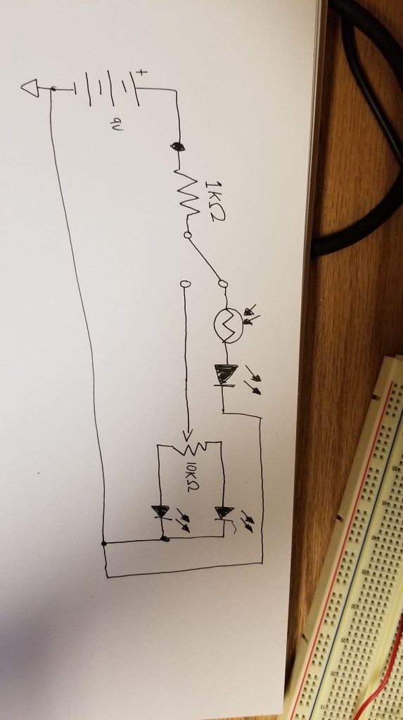
Resistor 1:
Color Code: Red Red Orange Gold
Stated Resistance Value: 22,000 ohms
Tolerance: 5%
Min/Max Possible Resistance Value: 20,900-22,100 ohms
Actual measured resistance: 21.69k ohms
Resistor 2:
Color Code: Brown Black Gold
Stated Resistance Value: 100 ohms
Tolerance: 5%
Min/Max Possible Resistance Value: 95-105 ohms
Actual measured resistance: 97.7 ohms
Resistor 3:
Color Code: Brown Black Green Gold
Stated Resistance Value: 1,000,000 ohms
Tolerance: 5%
Min/Max Possible Resistance Value: 950,000-1,050,000 ohms
Actual measured resistance: 1.013 million ohms
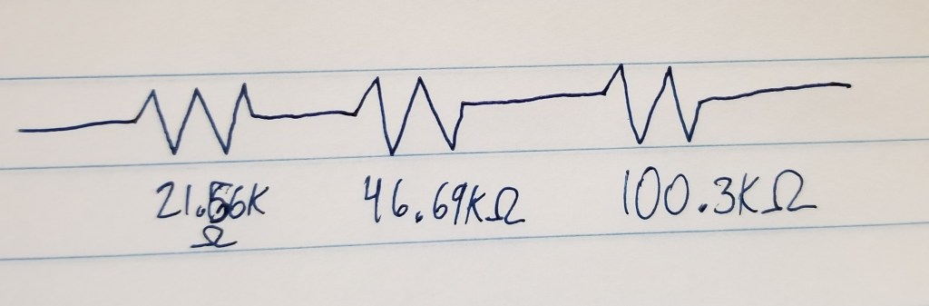
Red Red Orange Gold
Stated: 22k ohms
Measured: 21.56k ohms
Yellow Brown Orange Gold
Stated: 47k ohms
Measured: 46.69k ohms
Brown Black Yellow Gold
Stated: 100k ohms
Measured: 100.3k ohms
Calculated: 168,550 ohms = 21.56k + 46.69k + 100.3k
Measured: 158,300 ohms
3.
Red Red Orange Gold
Stated: 22k ohms
Measured: 21.56k ohms
Yellow Brown Orange Gold
Stated: 47k ohms
Measured: 46.69k ohms
Brown Black Yellow Gold
Stated: 100k ohms
Measured: 100.3k ohms
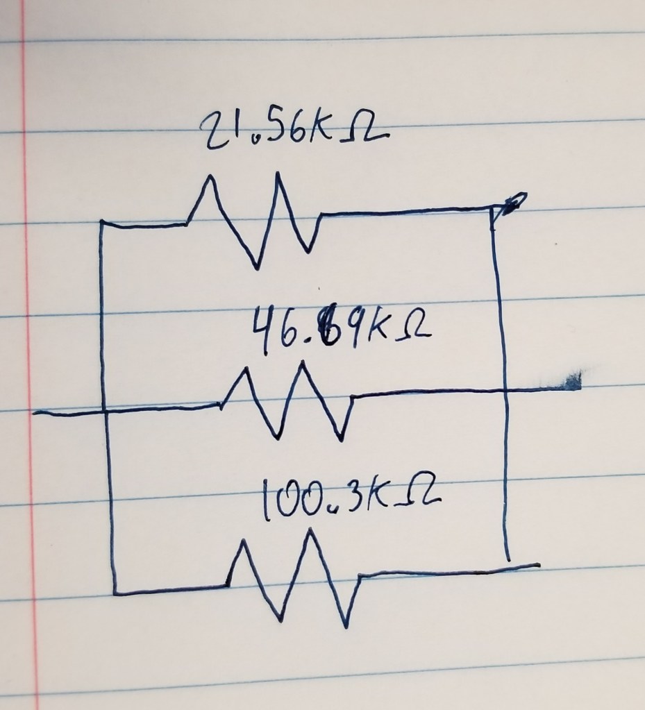
Calculated: 12,858.41 ohms = 1/((1/21.56k)+(1/46.69k)+(1/100.3k))
Measured: 12,900 ohms
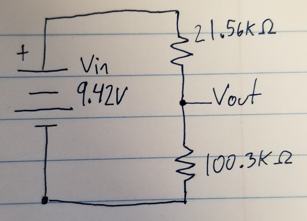
4.
Calculated: 7.753V = 9.42 x 100.3k / (21.56k + 100.3)
Measured: 7.74V
5.
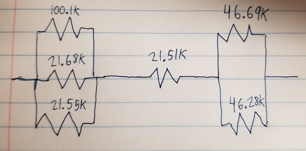
Calculated: 54,506.3199 = (1/(1/100.1k + 1/21.68k + 1/21.55k)) + 21.51k + (1/(1/46.69k) + (1/46.28k))
Measured: 54560
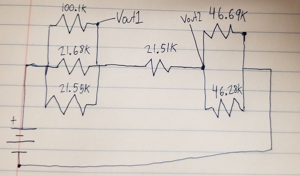
6.
VOut1
Calculated: 7.73V = 9.42 x ((1/(1/46,690)+(1/46,280)) + 21,510) / ((1/(1/100,100)+(1/21,680)+(1/21,550)) + 21,510 + (1/(1/46,690)+(1/46,280))
Measured: 7.77V
VOut2
Calculated: 4.01V = 9.42 x (1/(1/46,690)+(1/46,280)) / ((1/(1/100,100)+(1/21,680)+(1/21,550)) + 21,510 + (1/(1/46,690)+(1/46,280))
Measured: 4.031V
7.
V1
Calculated: 2.27 = 9.48 x 21,550 / (21,550 + 21,510 + 46,690)
Measured: 2.27
V2
Calculated: 2.27 = 9.48 x 21,510 / (21,550 + 21,510 + 46,690)
Measured: 2.26
V3:
Calculated: 4.93 = 9.48 x 46,690 / (21,550 + 21,510 + 46,690)
Measured: 4.91